
-
- Products
- Indoor Household Cords
- Appliance Cords
- General Purpose Short-Length Cords
- General Purpose Extension Cords
- Landscape & Decorating Cords
- Bright Color Extension Cords
- Oil-Resistant Extension Cords
- Cold-Flex Extension Cords
- VividFlex Power Cords
- EXTREME All-Weather Cords
- Cord Management
- Task Lights
- Adapters & GFCI Devices
- Where to Buy
- About
- Careers
- Glossary
- Catalog


What Is a Charging Station and How Does It Work?
A Charging Station is more than a parking space with a cable. It is a controlled link between an electricity supply and an electric vehicle’s battery. Inside, power electronics regulate voltage and current. Communication systems also confirm that the vehicle is connected safely. Some stations use alternating current from the grid. Others convert electricity into direct current before it reaches the battery.
Fatih Birol, Executive Director of the International Energy Agency, stated, “The rise of electric cars is unstoppable.” His observation explains why charging infrastructure matters. A home charger may deliver energy slowly overnight. A public fast charger can add substantial range during a short break. The actual speed depends on the vehicle, battery temperature, charger rating, and available grid capacity. Numbers can mislead.
The process begins when the driver plugs in. The station and vehicle exchange information before charging starts. Sensors check connection quality, temperature, and electrical limits. A payment system may authorize the session. The charger then supplies power while continuously adjusting its output. When the battery reaches its limit, charging slows or stops.
The experience is not always perfect. A busy station may have a queue. A damaged connector can interrupt a session. Software errors still happen. These practical weaknesses deserve attention, not marketing language. Reliable Charging Station design requires clear instructions, visible status signals, regular maintenance, and accessible support. Understanding these details helps drivers choose the right station and use it with greater confidence.
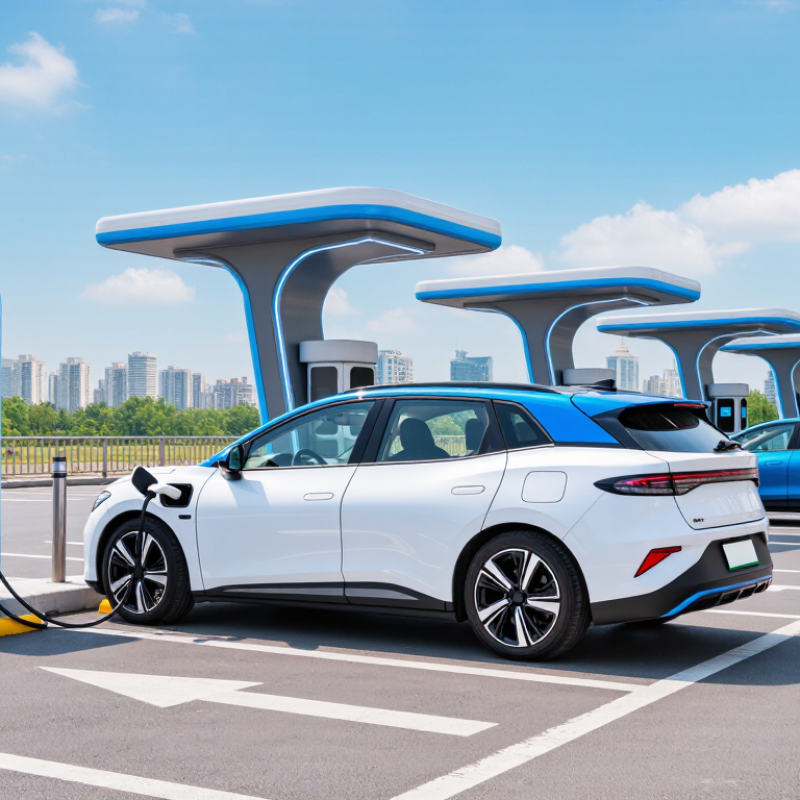
Table of Contents [Hide]
Define Charging Stations: EVSE, Plugs, and SAE Charging Levels
What Is a Charging Station and How Does It Work?
A charging station is more accurately called electric vehicle supply equipment, or EVSE. It delivers electricity safely and communicates with the vehicle before charging begins. A typical unit checks the connection, confirms that the cable is locked, and controls current flow. It does not always convert electricity itself. During AC charging, the vehicle’s onboard charger changes alternating current into battery-ready direct current.
The plug depends on the vehicle and charging network. SAE J1772 is widely used for AC charging in North America, while CCS combines an AC connector with additional DC pins. Other regions use different standards, and adapters may not support every function. Check the vehicle manual before connecting. A loose plug can stop a session.
SAE charging levels describe power, not simply charging speed. Level 1 uses a standard household outlet and usually adds only a few miles per hour. Level 2 uses higher-voltage AC equipment and can add much more range during a workday. DC fast charging sends direct current to the battery, reducing conversion time inside the vehicle. It is often called Level 3, although technical documents may classify DC levels differently. The terminology is not perfectly tidy. Temperature, battery percentage, cable limits, and vehicle software also affect actual speed. A display showing high power does not guarantee constant charging performance.