
-
- Products
- Indoor Household Cords
- Appliance Cords
- General Purpose Short-Length Cords
- General Purpose Extension Cords
- Landscape & Decorating Cords
- Bright Color Extension Cords
- Oil-Resistant Extension Cords
- Cold-Flex Extension Cords
- VividFlex Power Cords
- EXTREME All-Weather Cords
- Cord Management
- Task Lights
- Adapters & GFCI Devices
- Where to Buy
- About
- Careers
- Glossary
- Catalog


7 Tips for Choosing a Pipe Swaging Machine?
Choosing a Pipe Swaging Machine is a production decision, not merely a purchase decision. The correct model must match tube material, diameter range, wall thickness, output volume, and required finish. A machine that looks powerful may still create ovality, surface marks, or inconsistent joints.
Industry reports support this cautious approach. Grand View Research identifies automation, precision forming, and energy efficiency as major trends in the global metal forming machine market. The International Federation of Robotics also reports continuing growth in industrial automation, especially where repeatability and labor efficiency matter. These trends affect swaging workshops directly. However, market forecasts are not machine specifications. They cannot replace a sample test with your actual tubing.
Professor Matthias Merklein, a respected metal-forming researcher at Friedrich-Alexander-Universität Erlangen-Nürnberg, has emphasized, “The whole process chain must be considered.” That principle belongs at the center of every buying decision. Consider tooling changes, lubrication, noise, maintenance access, operator training, and after-sales support. Small details matter. A ten-minute setup delay can become hours of lost output each week.
This guide presents seven practical tips for choosing a Pipe Swaging Machine. It examines capacity, control systems, tooling flexibility, safety design, operating costs, and supplier credibility. No checklist is perfect. I have seen buyers focus heavily on rated force and overlook service response time. That shortcut can be expensive. Compare verified test results, request trial samples, and question every impressive specification before signing an order.
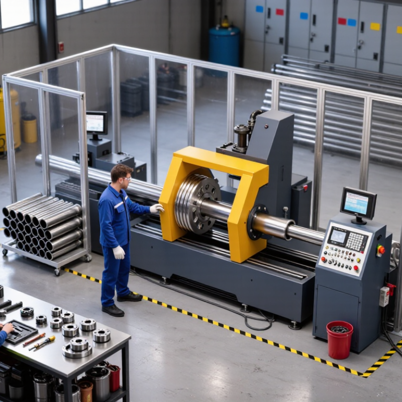
Table of Contents [Hide]
Understand the Pipe Swaging Machine’s Purpose and Operating Principles
A pipe swaging machine reshapes a pipe end by reducing or forming its diameter through controlled pressure. It usually works with dies that compress the tube evenly around its circumference. That is the core job.
Unlike cutting, swaging changes the metal without removing material. The forming action may be radial, axial, or a combination of both. Die movement, feed speed, lubrication, and material hardness all affect the final shape. Excessive force can create wrinkles, cracks, or uneven wall thickness. Poor alignment may leave the pipe visibly off-center. Small details matter.
When choosing a machine, match its working range to the pipe’s material, outside diameter, wall thickness, and required profile. More capacity is not always better. A machine with excessive force may reduce control on smaller tubes. Check adjustment accuracy, die replacement time, guarding, and emergency controls. These features influence daily reliability, not just purchase cost.
I once underestimated the effect of surface condition during forming. A slightly contaminated pipe caused inconsistent results. That mistake showed me why cleaning and inspection belong in the operating process. Test a sample piece before production, then measure diameter, length, and wall thickness at several points. Review the results against approved drawings and technical requirements. Some machines also need trial adjustments because real material rarely behaves exactly like a catalog example.