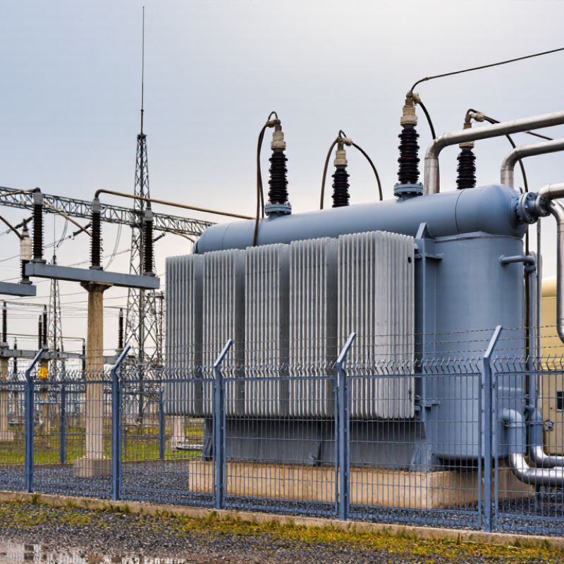
| Transformer Application | Step-down power transformer | Reduce high transmission or subtransmission voltage to a lower distribution voltage. | Alternating current in the high-voltage winding produces a changing magnetic flux in the core, inducing a proportional voltage in the low-voltage winding. | Power flow is bidirectional in some systems, so transformer ratings and protection may need to support reverse power flow. |
| Common Voltage Ratios | 69/13.8 kV, 115/13.8 kV, 138/13.8 kV, 230/69 kV | Match the transformer to the connected transmission, subtransmission, and distribution networks. | The turns ratio determines the approximate voltage conversion according to the relationship between primary and secondary winding turns. | Actual ratings vary by utility network, system voltage, grounding method, and load requirements. |
| Rated Power | Approximately 10–500 MVA for many substation applications | Define the continuous apparent-power capacity of the transformer. | The rating is limited mainly by winding temperature rise, insulation thermal aging, cooling capability, and permissible loading conditions. | Large transmission transformers can exceed this range; emergency or short-time loading must follow the manufacturer’s thermal limits. |
| Frequency | 50 Hz or 60 Hz | Ensure compatibility with the connected power system. | The alternating frequency determines the magnetic flux behavior in the core and influences core size, losses, and heating. | A transformer should not be operated outside its design frequency and volts-per-hertz limits. |
| Voltage Regulation | Typically about 5–15% from no-load to full-load, depending on design and power factor | Control the secondary voltage as load current and power factor change. | Winding resistance and leakage reactance create voltage drop under load. A tap changer adjusts the effective turns ratio to compensate for this drop. | Regulation is affected by load magnitude, load power factor, transformer impedance, and tap position. |
| On-Load Tap Changer (OLTC) | Common range: approximately ±10% in 1.25% steps | Change the voltage ratio while the transformer remains energized and supplying load. | A diverter switch and tap selector transfer current between winding taps while limiting interruption and preventing short circuits between adjacent taps. | OLTC equipment requires mechanical inspection, contact maintenance, and monitoring of switching operations and oil condition. |
| De-Energized Tap Changer | Usually several fixed tap positions, often in 2.5% or 5% increments | Set the voltage ratio for the expected system voltage when the transformer is not energized. | The tap position changes the number of active winding turns, but the transformer must be isolated and grounded before operation. | It is not suitable for routine voltage adjustment during normal energized operation. |
| Cooling Method: ONAN | Oil Natural, Air Natural | Remove heat from the core and windings by natural circulation. | Transformer oil circulates by convection through radiators, while surrounding air removes heat from the radiator surfaces by natural convection. | Common for base-load operation; available capacity depends on ambient temperature and radiator condition. |
| Cooling Method: ONAF | Oil Natural, Air Forced | Increase transformer capacity by improving heat transfer through fans. | Oil continues to circulate naturally, while fans force air across the radiators or cooler banks. | Fan control may be based on winding or oil temperature; fan failure can reduce the permitted transformer loading. |
| Cooling Method: OFAF / OFWF | Oil Forced, Air Forced / Oil Forced, Water Forced | Provide high-capacity heat removal for large transformers or restricted installation areas. | Pumps circulate oil through external heat exchangers. Air fans or cooling water then remove heat from the oil. | Pumps, fans, heat exchangers, and water systems require auxiliary power, alarms, and redundant or supervised controls where necessary. |
| Insulation System | Mineral insulating oil with cellulose-based solid insulation | Prevent electrical breakdown between windings, turns, the core, and the grounded tank. | Liquid insulation fills spaces around the windings and transfers heat, while solid insulation provides mechanical support and dielectric separation. | Moisture, oxygen, contamination, overheating, and electrical stress accelerate insulation aging. |
| Insulating Oil Functions | Dielectric medium and heat-transfer fluid | Provide electrical insulation and transport heat to radiators or coolers. | Oil circulates through winding ducts and radiator circuits, carrying heat away from active parts. | Common condition tests include breakdown voltage, water content, acidity, power factor, and dissolved-gas analysis. |
| Conservator and Breather | Expansion tank with silica-gel breather | Accommodate oil volume changes and limit moisture entry. | Oil expands into the conservator as temperature rises. The breather filters and dries air entering or leaving the tank. | Breather desiccant should be inspected and replaced or regenerated when moisture saturation is indicated. |
| Buchholz Relay | Gas-actuated relay for conservator-type transformers | Detect internal faults and abnormal oil movement. | Slow gas accumulation can produce an alarm, while a sudden oil surge caused by a serious internal fault can initiate a trip. | It is installed in the pipe between the main tank and conservator and is not normally used on sealed-tank designs without a conservator. |
| Differential Protection | High-speed transformer differential relay | Detect internal phase-to-phase, phase-to-ground, and winding faults. | Currents entering and leaving the protected transformer zone are compared after compensation for ratio, phase shift, and CT characteristics. | Percentage restraint helps prevent incorrect operation during external faults and transformer inrush conditions. |
| Overcurrent and Ground-Fault Protection | Phase overcurrent, residual or neutral overcurrent, and restricted earth-fault functions | Protect the transformer and connected circuits against excessive current and ground faults. | Protective relays operate circuit breakers when current exceeds configured pickup and time-current coordination limits. | Settings must coordinate with upstream and downstream protection while allowing permissible transformer energization and overloads. |
| Sudden-Pressure and Pressure-Relief Devices | Rapid pressure relay and pressure-relief device | Respond to rapid internal pressure increases and prevent tank rupture. | An internal fault can rapidly decompose oil and generate gas, increasing tank pressure. The devices provide an alarm, trip signal, or controlled pressure release. | Pressure-relief discharge paths must remain unobstructed, and device operation should be checked during inspections. |
| Temperature Monitoring | Top-oil temperature indicator and winding hot-spot indicator | Monitor thermal loading and prevent excessive insulation aging. | Sensors measure or calculate oil and winding temperatures and can control cooling stages or initiate alarms and trips. | Hot-spot temperature is more closely related to insulation aging than average oil temperature. |
| Surge Protection | Metal-oxide surge arresters at suitable line terminals | Limit temporary and transient overvoltages caused by lightning or switching operations. | The arrester conducts surge current to ground when voltage rises above its protective level and returns to a high-resistance state afterward. | Arrester grounding connections should be short, direct, and properly coordinated with transformer insulation levels. |
| Grounding | Tank grounding, neutral grounding, and station grounding grid | Provide a safe path for fault current and control touch and step voltages. | Metallic parts are bonded to the station grid, while transformer neutrals may be solidly grounded or connected through an impedance. | Grounding design depends on system fault current, neutral configuration, soil resistivity, and protection requirements. |
| Typical Losses | No-load losses and load losses | Represent energy dissipated during energized operation and load current flow. | No-load losses mainly arise in the magnetic core, while load losses are produced by winding resistance, stray flux, and structural eddy currents. | Losses increase operating cost and heat production; efficiency is generally highest near the transformer’s normal design loading range. |
| Routine Condition Monitoring | Oil tests, dissolved-gas analysis, infrared inspection, leak checks, and electrical tests | Identify developing insulation, thermal, mechanical, and connection problems. | Changes in gas composition, temperature, oil quality, winding resistance, or insulation power factor can indicate abnormal conditions. | Testing intervals should reflect transformer age, loading, fault history, criticality, and applicable maintenance procedures. |