
-
- Products
- Indoor Household Cords
- Appliance Cords
- General Purpose Short-Length Cords
- General Purpose Extension Cords
- Landscape & Decorating Cords
- Bright Color Extension Cords
- Oil-Resistant Extension Cords
- Cold-Flex Extension Cords
- VividFlex Power Cords
- EXTREME All-Weather Cords
- Cord Management
- Task Lights
- Adapters & GFCI Devices
- Where to Buy
- About
- Careers
- Glossary
- Catalog


What Is an LED Linear Module?
An LED linear module is a long, narrow lighting assembly designed to produce an even line of light. It typically contains LEDs mounted on a circuit board, with electrical connections and, in some designs, optical components. The module may sit inside an aluminum channel or a complete luminaire. A diffuser can soften visible points of light, while the housing helps manage heat. Small details matter.
The term is not perfectly standardized. Some suppliers use “LED linear module” for the light-engine board alone; others mean a board combined with optics or mounting parts. Check the product drawing, dimensions, voltage, current, and compatible driver before choosing one. Also review the stated operating temperature and installation guidance. A module that fits the channel may still perform poorly if heat cannot escape or the driver is unsuitable.
In practical use, these modules appear in offices, shops, kitchens, and display cases, where continuous illumination can be more useful than isolated light spots. For example, a slim module beneath a cabinet can brighten a countertop without taking up much space. Results depend on layout, diffuser, and installation quality. Not every linear module produces perfectly uniform light, and a bright specification alone tells only part of the story. Understanding its construction and limits makes comparison more reliable.
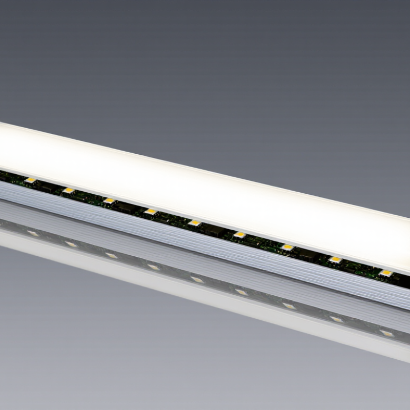
Table of Contents [Hide]
What an LED Linear Module Is Under IEC 62031
An LED linear module is a row-shaped light source containing LEDs on a circuit board, with electrical connections and supporting components. Under IEC 62031, it is treated as an LED module for general lighting, not automatically as a complete lamp or luminaire. The standard sets safety requirements for the module itself. It does not establish a universal efficiency level or prove that every finished fixture is safe.
IEC 62031:2018, including Amendment 1:2021, addresses risks such as electric shock, insulation failure, and excessive temperatures. Testing may examine construction, electrical protection, and heating under specified conditions. Details matter. A module that passes alone can still be used in a poorly designed luminaire. Fit, heat transfer, wiring, and the matched controlgear all affect the final product.
Efficiency figures offer useful context, but they answer a different question. The U.S. Department of Energy’s LED guidance reports that LEDs use at least 75% less energy and can last up to 25 times longer than incandescent lighting. Those comparisons describe lighting technology, not IEC 62031 compliance. A safety mark or test report should therefore be checked against the exact module model and its installation conditions. In practice, I would also review the temperature limits; they can be easy to overlook.