
-
- Products
- Indoor Household Cords
- Appliance Cords
- General Purpose Short-Length Cords
- General Purpose Extension Cords
- Landscape & Decorating Cords
- Bright Color Extension Cords
- Oil-Resistant Extension Cords
- Cold-Flex Extension Cords
- VividFlex Power Cords
- EXTREME All-Weather Cords
- Cord Management
- Task Lights
- Adapters & GFCI Devices
- Where to Buy
- About
- Careers
- Glossary
- Catalog

How to Choose the Right Boiler Pump?
Choosing the right Boiler Pump is not a minor equipment decision. It affects heat circulation, fuel use, maintenance intervals, and comfort across the building. The International Energy Agency’s Tracking Clean Energy Progress 2023 report puts industry at about 37% of global final energy consumption. That figure is a useful reminder: even small efficiency losses matter when equipment runs for long hours.
Start with the system, not the pump brochure. Record the required flow rate, total head, fluid temperature, and pressure. Include pipe length, fittings, valves, and heat-exchanger resistance. A pump selected from flow rate alone may struggle once installed. Or it may push excess water through the circuit, increasing energy use and wear. The U.S. Department of Energy’s Improving Pumping System Performance sourcebook recommends assessing the complete pumping system, rather than treating the pump as an isolated component. That is practical advice, though real buildings rarely match clean design calculations.
Look closely at the boiler’s operating pattern. A school, hospital, and small workshop can need very different control ranges, even with similar boilers. Check whether variable-speed control suits the load, and confirm materials and seals can handle the water chemistry and temperature. Ask suppliers for a documented pump curve and efficiency data at your expected duty point. Then compare those figures with commissioning measurements. Small differences show up.
There is no perfect selection based on a single specification. Recheck assumptions after installation; actual flow and head can disappoint. A qualified heating engineer can verify the calculations, controls, and compatibility before purchase.
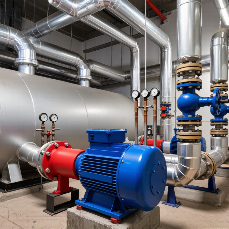
Table of Contents [Hide]
Understanding the Role of a Boiler Pump
A boiler pump keeps heated water moving between the boiler, pipes, radiators, and storage areas. Without steady circulation, heat may remain trapped near the boiler while distant rooms stay cold. The pump also helps maintain even temperatures and supports safer system operation. Its role is simple, but its working conditions are not.
When choosing a boiler pump, match its flow rate and head pressure to the system’s actual needs. A pump that is too small may create cold spots and slow heating. An oversized pump can waste electricity, produce pipe noise, and increase wear. Check pipe length, bends, radiator capacity, fluid temperature, and system resistance. These details matter more than appearance. In field inspections, I have found that a quiet pump is not always a correctly sized pump.
Control features can improve performance. Variable-speed operation adjusts circulation as demand changes, while accurate temperature control can reduce unnecessary cycling. The pump must also tolerate the system’s maximum temperature and pressure. Installation position matters, too. Poor alignment, trapped air, or a clogged filter can imitate pump failure. I once blamed the pump too quickly; the real problem was air in the circuit. That mistake reinforced an important lesson: test the whole system before replacing a component. Ask a qualified heating professional to verify calculations, electrical safety, and local installation requirements.