
-
- Products
- Indoor Household Cords
- Appliance Cords
- General Purpose Short-Length Cords
- General Purpose Extension Cords
- Landscape & Decorating Cords
- Bright Color Extension Cords
- Oil-Resistant Extension Cords
- Cold-Flex Extension Cords
- VividFlex Power Cords
- EXTREME All-Weather Cords
- Cord Management
- Task Lights
- Adapters & GFCI Devices
- Where to Buy
- About
- Careers
- Glossary
- Catalog


2026 Top Capacitors and Capacitance Types for Buyers
Capacitors And Capacitance are becoming strategic purchasing considerations as electronics become smaller, faster, and more power-conscious. Grand View Research identifies continued growth in the global capacitor market, supported by electric vehicles, renewable-energy systems, industrial automation, and consumer electronics. Fortune Business Insights also highlights increasing demand for multilayer ceramic capacitors, aluminum electrolytic capacitors, and film capacitors across power and control applications. These trends matter to buyers because component selection affects reliability, heat management, filtering performance, and total ownership cost.
The market is not simple.
A ceramic capacitor may fit a smartphone power rail, while a film capacitor may better serve an inverter DC link. Aluminum electrolytics still offer useful capacitance density, especially in power supplies, but their lifetime can change sharply with temperature and ripple current. Tantalum and polymer capacitors may provide stable performance in compact circuits, yet their voltage derating and failure behavior require careful review. Yole Group’s electronics research repeatedly points to automotive electrification and power semiconductor growth as major drivers for advanced passive components. Buyers should connect these forecasts with actual datasheet evidence, not marketing claims.
This 2026 guide compares major capacitor and capacitance types through practical purchasing criteria. It examines rated voltage, tolerance, equivalent series resistance, ripple current, leakage current, temperature range, aging, package size, and supply continuity. IEC 60384 standards and AEC-Q200 qualification provide useful reference points for reliability evaluation. Still, no universal winner exists. A capacitor selected only by price can create hidden redesign costs, and even reputable reports cannot replace circuit-level testing. Wise procurement combines supplier history, validated samples, lifecycle data, and application experience. That approach is less dramatic, but usually more dependable.
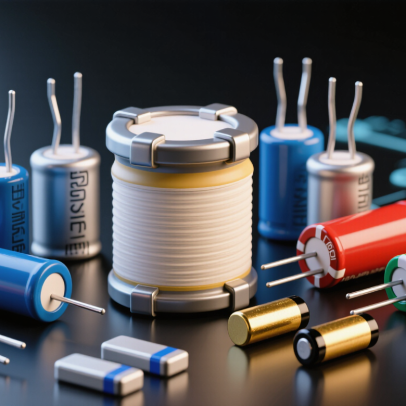
Table of Contents [Hide]
Capacitance Basics: Farads, C = εA/d, and DC-Bias Derating
For buyers, capacitance begins with charge storage. One farad stores one coulomb at one volt. The practical equation is C = εA/d. Higher dielectric permittivity, larger electrode area, or thinner spacing increases capacitance. Each choice affects voltage strength, heat, and reliability.
DC bias can quietly reduce a ceramic capacitor’s usable value. A part marked 10 µF may deliver far less at its rated voltage. Check the capacitance curve at the actual operating bias and temperature. A 5 V rail, 3.3 V rail, and 48 V bus require different verification habits. Tolerance alone is not enough. This is where many purchasing decisions become too optimistic.
Application demand is rising. The International Energy Agency’s Global EV Outlook 2025 reports more than 17 million electric cars were sold in 2024, increasing demand for compact power electronics. The U.S. Department of Energy’s Energy Storage Grand Challenge Roadmap also emphasizes higher efficiency, safety, and lifecycle performance in energy systems. Buyers should compare ripple current, ESR, leakage, aging, and derating data, not only farads per dollar. Measurements can disagree with the datasheet. That possibility deserves attention.